
Last updated:
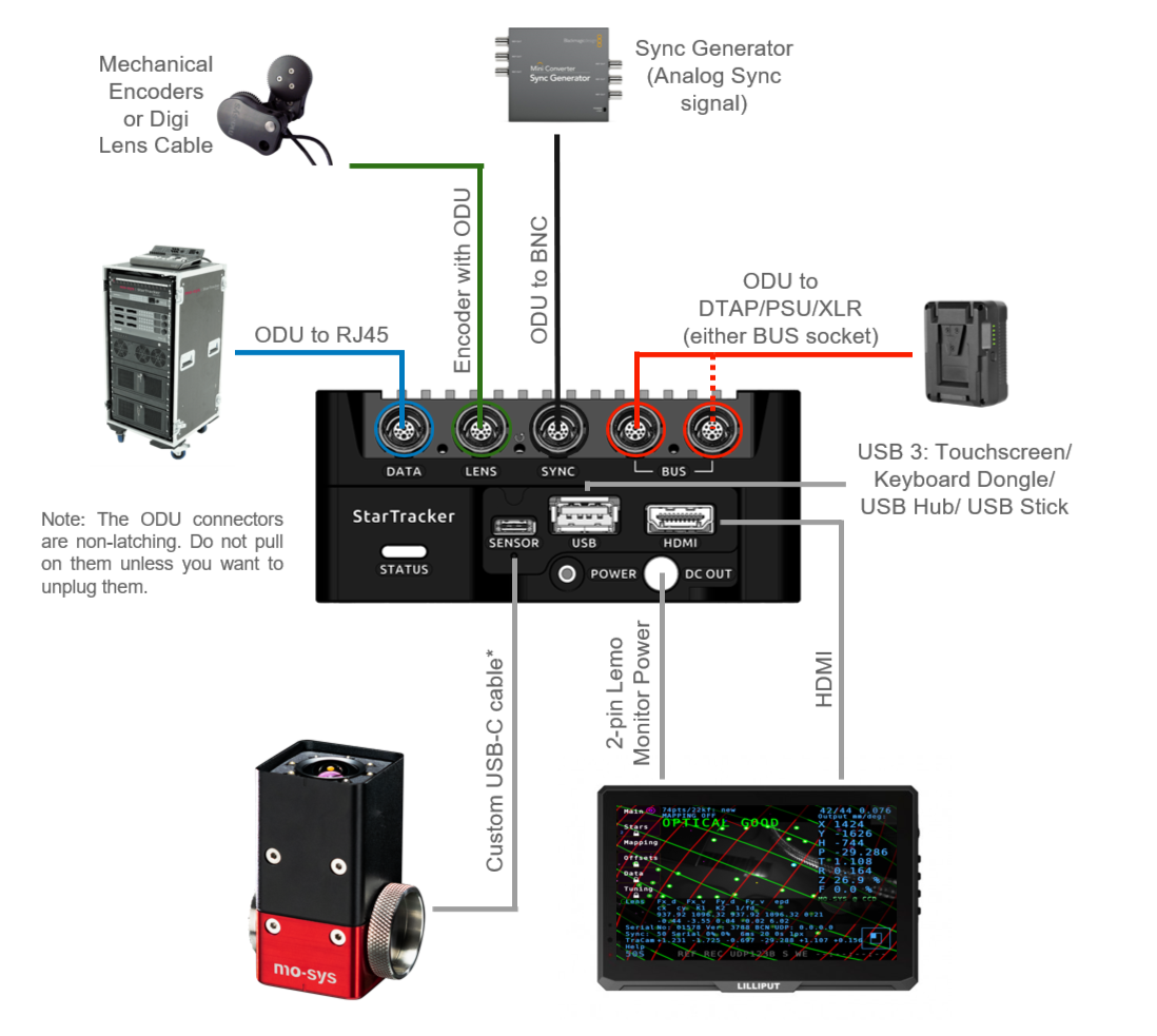
StarTracker Processor
StarTracker Sensor
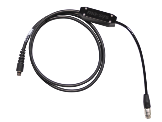
Sensor Umbilical (USB-C - 40cm)
Sensor Umbilical (USB-C - 200cm)
Power Supply/D-Tap
ODI D-Tap Cable (50cm)
Wireless Keyboard
ODU Network Cable (RJ45 - 25cm)
Female to Female RJ45
ODU Sync Cable (BNC - 20cm)
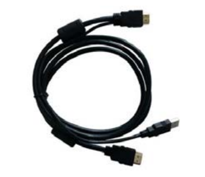
HDMI/USB Cable (150cm)
Monitor Power Cable (75cm)
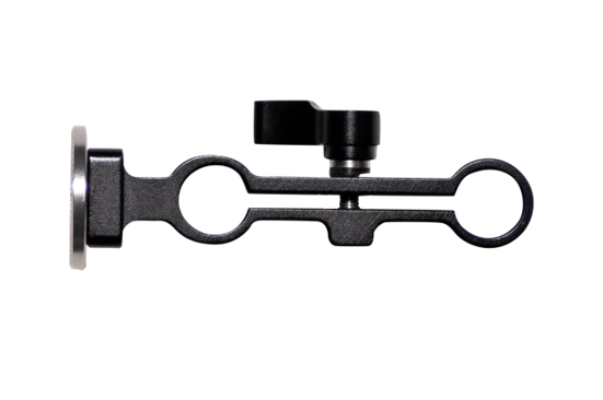
Magic Arm
HDMI Touchscreen
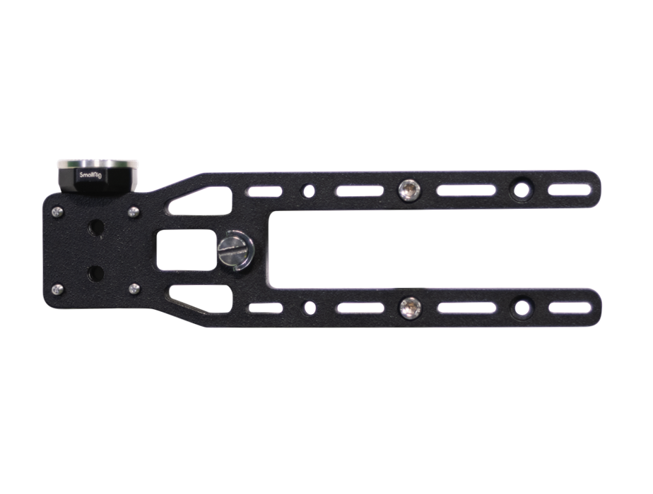
Broadcast Mounting Bracket
15mm Rod Processor Bracket
15mm Rod Sensor Bracket
Tools
USB Hub
USB Stick
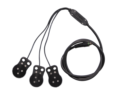
Lens Encoders (100cm Z/F)
Lens Encoders (100cm Z/F/I)
Canon/Fujinon/Film Gears
ODU Fujinon Digi Cable (100cm)
ODU Canon Cable (100cm)
ODU Canon 18-80 Cable (100cm)
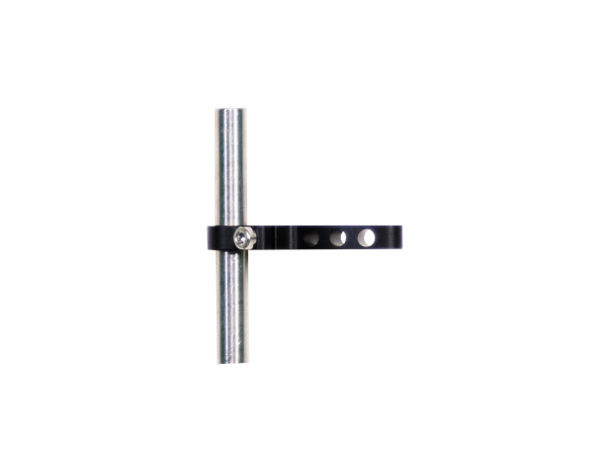
19mm Rod Lens Encoder Clamp
15mm Rod Lens Encoder Clamp
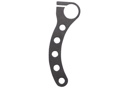
ENG Lens Mount Bracket
ODU to XLR
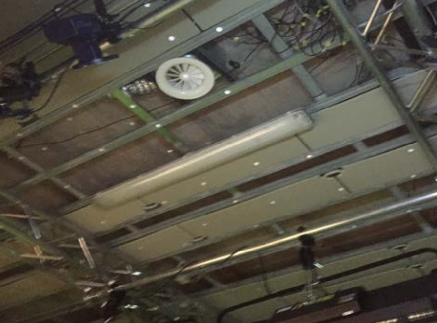
Stars may be applied to ceiling lighting grids, AC ducts and other rigid structures that remain permanently static, for the lifetime of map usage.
Ideally StarTracker requires sight of at least 11 stars at any one time, any fewer will cause tracking loss, 30 or more stars provide robustness to occlusions.
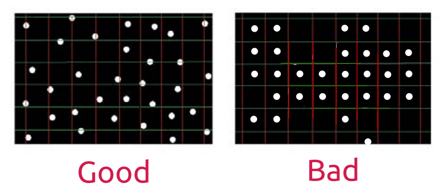
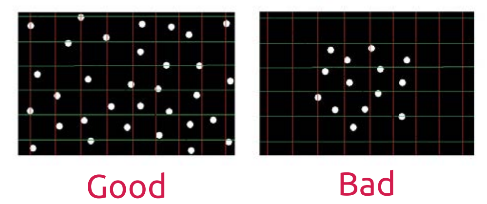
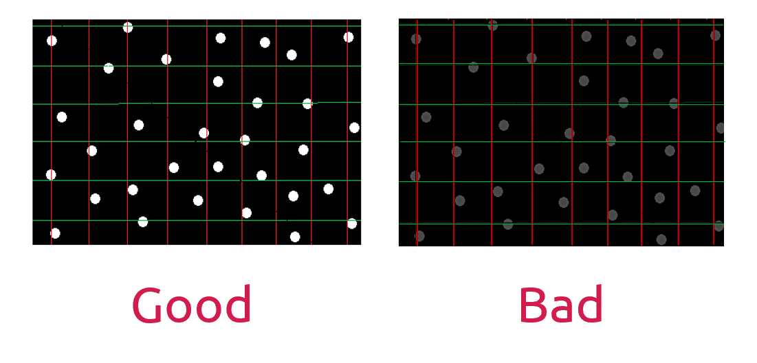
Stars should be placed randomly. Do not create a pattern or StarTracker will have problems finding the map and loose tracking.
Stars should be clearly visible, though it’s normal for some to be hidden and revealed by lights and structures during operation.
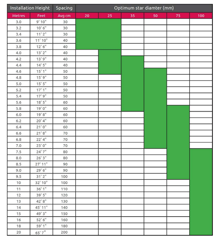
Use larger stars as ceiling height increases, with a proportionate increase in spacing. Accuracy is improved by applying stars at multiple ceiling heights. Use at least 10% height difference though this is less important below 4m (See Star Chart).
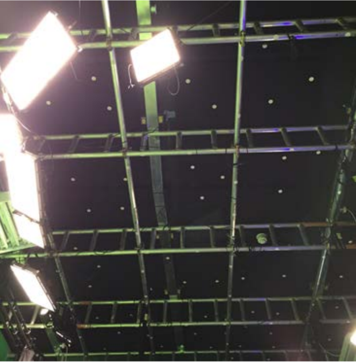
An example of a 5-metre-high ceiling. The stars are positioned randomly with ideal spacing across the ceiling and lighting grid. The reflective metal surfaces do not present a problem for the StarTracker sensor.
4m high ceiling with sloping air duct dropping to below 3m.With such little height variation, within 1m,the stars do not need to be of differing diameters. Density can increase on the lower duct; notice the random placement. Installation extends to the boundary of the studio giving ideal coverage.
A 5m high ceiling with a lighting grid at 4 metres. Average height is therefore 4.5 metres with ideal star size of 35mm.
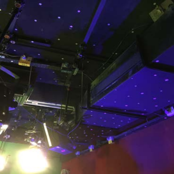
Stars are randomly placed on the ceiling, lighting grid and fixed pipes. Most are placed on horizontal surfaces, though several are placed on angled surfaces proving useful when the camera operates with a high degree of tilt. The star height variation in the studio assists tracking accuracy.
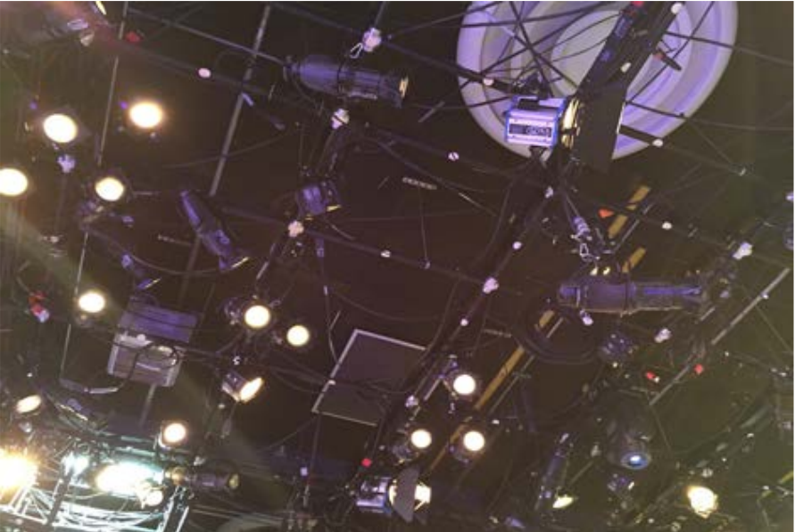
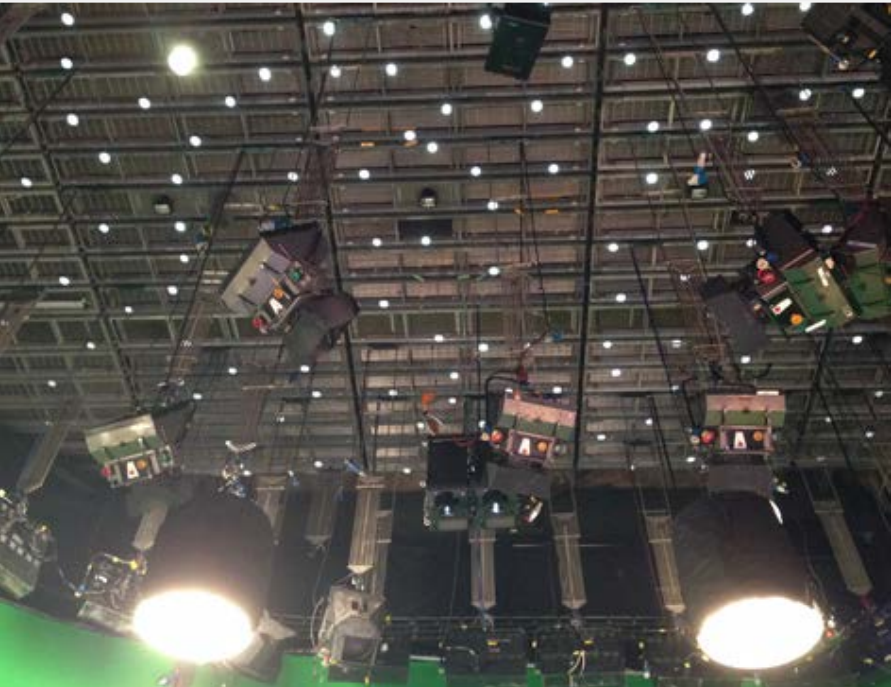
In this 5m high studio installation there are far too many stars being compromised by cables in front of them, within 5cm. This should be avoided. Spacing on the truss is good.
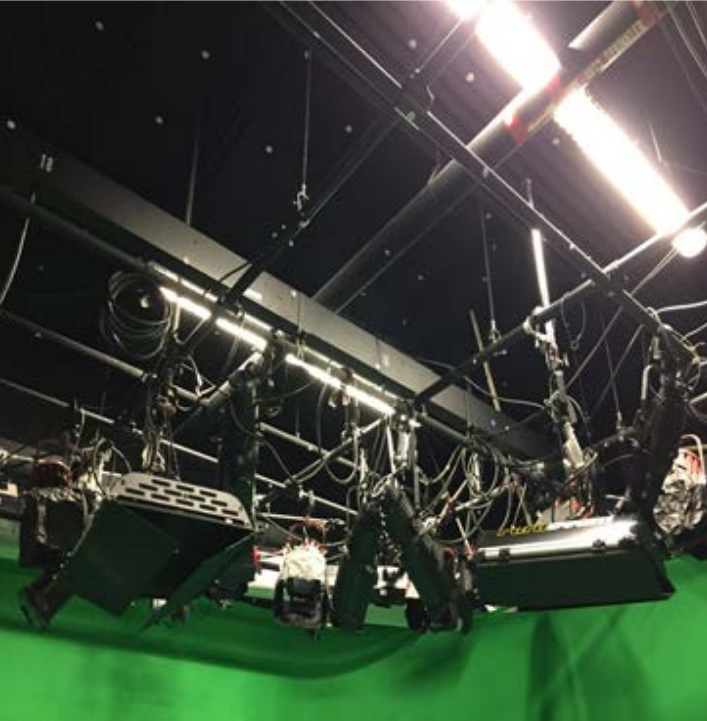
The large amount of metal objects do not present a problem for detection. Height variation is low; however, tracking is good due to low ceiling height at 4m. Notice star placement on the air condition vent; almost any fixed structures are suitable for mounting stars. Avoid cable tangles as placing stars directly behind these will hide stars from almost any viewing angle rendering them useless to StarTracker.
Notice star placement on the air condition vent; almost any fixed structures are suitable for mounting stars. Avoid cable tangles as placing stars directly behind these will hide stars from almost any viewing angle rendering them useless to StarTracker.
Some of the stars, shown here, are closer than recommended for this 10m, however, the StarTracker is tolerant allowing for continued operation. We recommend a minimum distance of 75cm between stars at a height of 10 metres, ideally placing stars at multiple heights to increase accuracy.
To make changes to hardware settings, or anything that is outside the StarTracker GUI and that is modified in the operating system (software installs, WiFi settings) you need to boot into Engineering mode.
For that keep tapping up-key during start-up immediately after powering up the unit.
Keep pressing the up-key every 20 seconds, until you see the boot menu.
Choose “Engineering Mode” from the menu. The StarTracker software will be launched automatically.
You can tell it is in Engineering mode by the orange border around the StarTracker GUI and the “ENGINEERING MODE” indicator under the optical status.
It is rare to use it for standard operations in the StarTracker, this includes network settings, StarTracker software updates, copying maps and config files. In the manual we will tell you when to boot into Engineering mode.
To learn how to set up Wi-Fi for remote support go to Troubleshooting section at the end.
To turn on shortcut keys go to Main → Shortcuts - “O” Toggle on / off the optical sensor camera - “S” Save Map - “R” Reset/unload map - “L” Load Map - “A” Refresh estimated star detection - “Y” Yes / confirm - “N” No / cancel operation - “I” Toggle on/ off IMU (gyro) - “Esc” Closes current open menu/ cancel current operation
StarTracker comes with touch screen capabilities. When you get your system, you shall have a Lilliput LCD monitor, and an HDMI cable with a USB attached to it.
To enable the touch screen component, you will need to plug the USB cable into one of the USB ports on the StarTracker.
Once plugged in, you will be able to go through the StarTracker menus via touch screen.
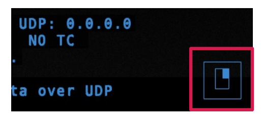
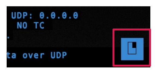
To take the lock function off, you will need to touch the bottom right that looks like a right click on a mouse. This will be highlighted, and you will be able to unlock a menu.
NOTE: After using the right click touch function, It will turn back off. So, to continue to unlock menus of the StarTracker, you MUST hit the right click button again.
Everything is as functional as if it were a keyboard, and if you want to leave or close the menu, you will need to double tap the right click button. This will act as an “ESC” key.
If you hold the bottom right for longer than 3 seconds, all main menus will unlock.
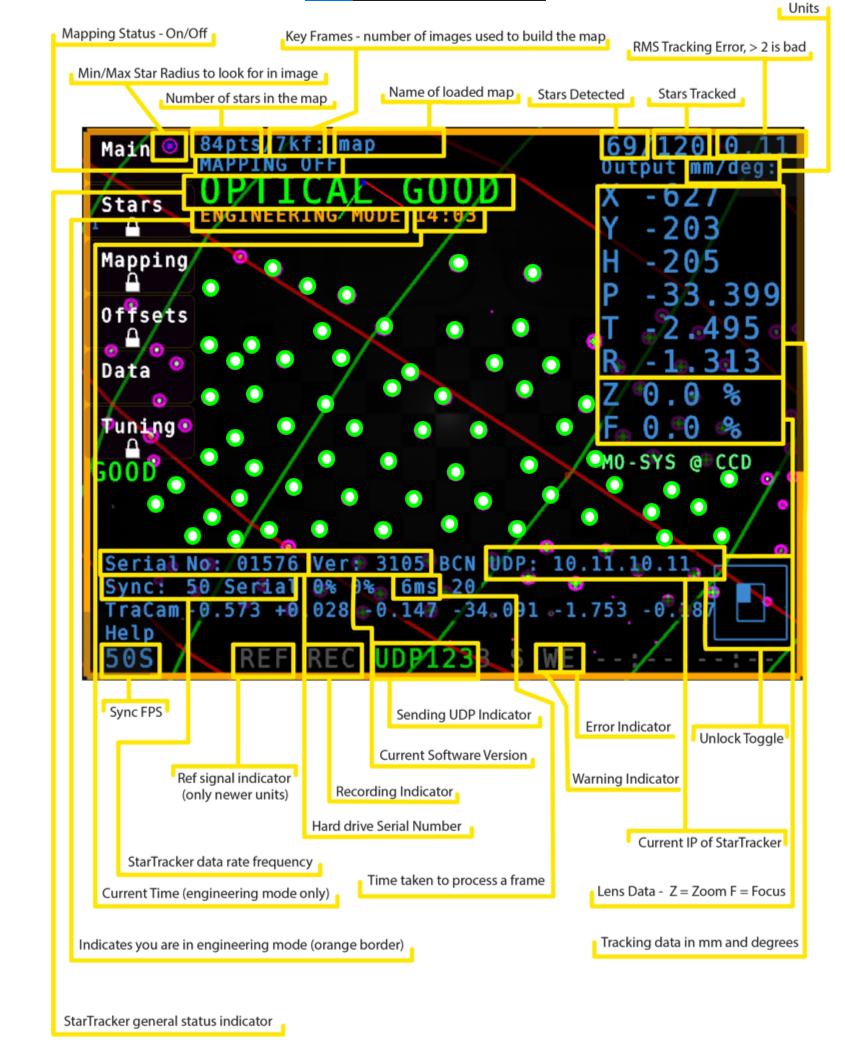
To switch between the Data Output Display modes touch the top right.
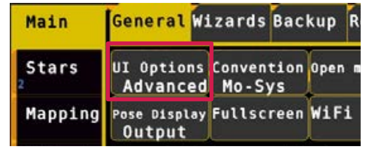
In Main → General → UI Options you can switch between displaying basic functions or advanced functions for all the menus. When choosing Basic, all the advanced functions are blacked out. Basic functions are sufficient for most StarTracker installations and daily operation. We recommend using Basic and only, if necessary, switch to Advanced.
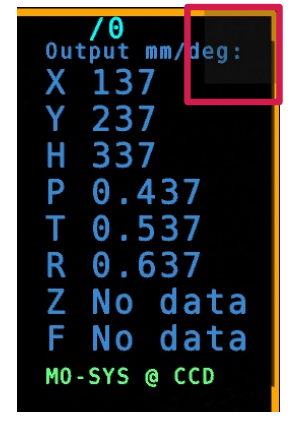
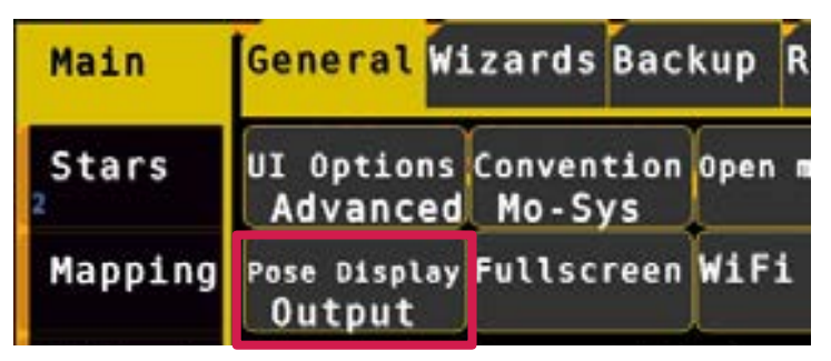
You can choose between 3 display modes for the data in Main → General → Pose Display (or click/touch top right corner)
Off – doesn’t show anything, so you can see stars behind it
TrackCam – it’s cyan colored, shows position of StarTracker sensor camera (MoSys @ Sensor)
Output – it’s blue, shows position of broadcast/film camera (i.e., StarTracker with gyro filters and offsets applied), or test signal when relevant (Mo-Sys @ CCD).
![]()
When StarTracker is running without a loaded map a data stream is sent for test purposes only. The xx values increment continuously to provide data for test purposes. The first decimal place corresponds to the axis; X=0.1 Y=0.2 Z=0.3 P=0.4 T=0.5 R=0.6
The xx values will linearly ramp up after the first decimal place (e.g., from P=0.41 to P=0.49) so that you know that the data is continuously coming in.
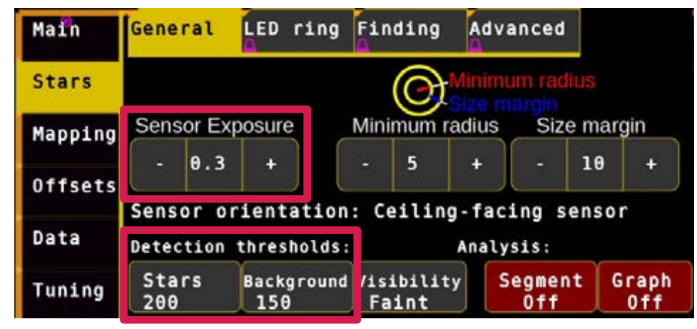
Adjust exposure, using trial and error, to gain best contrast between stars and background, accessed through the Stars General → Sensor Exposure buttons set the exposure level to 0.4 as a starting point. Visibility adjusted in Stars → General → Visibility should be set to Normal at this time.
If there are stars at the edge of the view that appear dim you can try to increase exposure.
In the Detection thresholds section, you can also set the Star Intensity and Background Intensity. This is useful if for example you have a bright background and you can’t lower the exposure.
The normal value of star intensity Stars is 100, and Background is 80. If the stars are not displayed brightly then Stars could be reduced to a min of 50. If the background is an unusually bright Background, it could be increased to a max of 170. Usually 100 / 80 suffices.
If a star has been detected two magenta circles will appear around it (may appear as one). This shows it is ready to be added to map. Stars that have no magenta circles will be ignored during the mapping process.
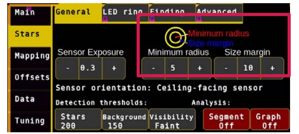
Star radius detection is set automatically but if you would like to experiment with adjusting star size to assist detection it can be accessed through Stars → General → Minimum Radius type a value between 3 and 15 (nominal 5) and hit Enter. Adjust this value, through trial and error, to build the largest constellation possible.
The Size Margin indicates the additional radius. E.g., if your minimum radius is 5 and your margin is set to 10, your maximum radius is 15.
You may notice circles next to the Main button. The largest circle is the maximum star radius that will be accepted. Stars slightly smaller than the inner most circle may still be accepted.
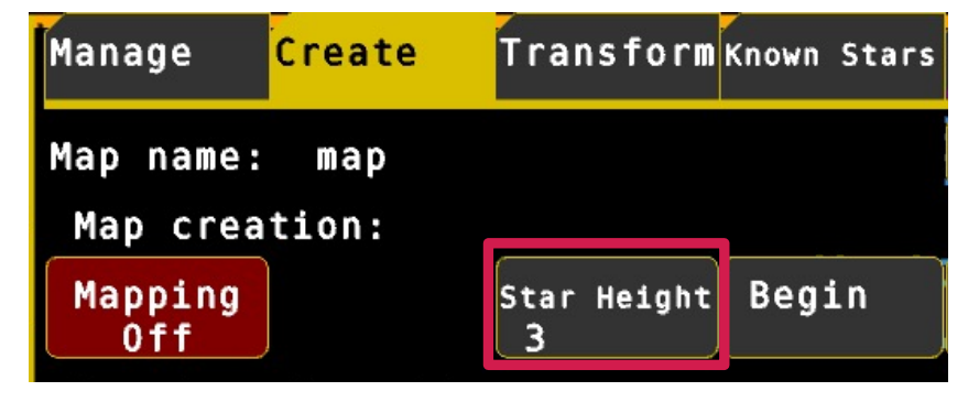
Enter the approximate height (in meters) of the reflective stickers from the StarTracker sensor camera to the stars:
Go to Mapping → Create , click Star Height.
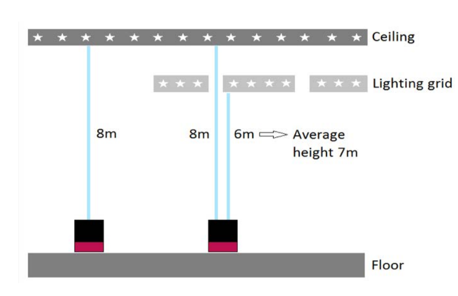
Enter the height value (in meters for example 2.5m) and hit Enter. If you have stars on more than one level use the average height. (Example: Stars on ceiling are 8m high, stars on lighting grid are 6m high -> Star height is 7m)
Info: This measurement does not have to be down to centimeter precision. You can allow an error of 5-10%. Meaning if you have a ceiling of 10.78m and you type in 10m it is still ok.
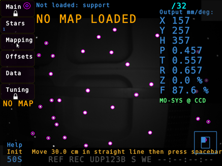
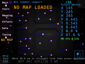
Reset mapping by pressing -R- and –Y- or clicking Mapping → Create → Unload Map then -Y- to confirm. (The status should appear as NO MAP LOADED)
Ensure Mapping is on: Go to Mapping → Create, locate Mapping Off, activate it by clicking on it, so it shows Mapping On
Click Change… next to map name.
Enter your map name (e.g. studio 2) in lower case and hit enter.
Hit spacebar or click Begin.
A flashing message at the bottom should tell you to move the StarTracker camera XX cm. The distance is related to the ceiling height you entered early. Use a tape measure for this procedure.
Move the StarTracker in a straight line by XXcm and hit spacebar or press Begin again. Try to avoid covering any of the stars, e.g. by standing in front of the sensor or the system will lose some of the star tracks. If the flashing message switches back to “Load map or press Spacebar to create a new map” the system has lost too many tracks or failed to start a new map. In this case try again. Press R and Y.
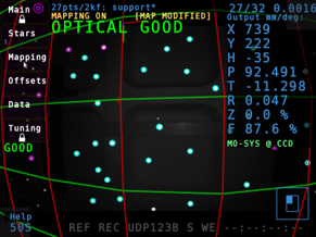
If successful, a green/red grid should appear on the screen, which indicates that you have an initial map. The grid line spacing of 1m also allows you to verify your map after it is fully calibrated.
If the grid appears too small and the output values for X, Y and H are too high, press R and Y and repeat from step 5.
You should now have a basic tracking map. This will be improved as more stars are discovered and captured.
To obtain optimum triangulation, walk around holding the sensor, pointing upwards, while moving up and down in height which assists detection through viewing stars from different angles.
Status should report OPTICAL GOOD at the beginning of the mapping process and as more stars are recorded tracking status will become a stable OPTICAL GOOD.
If status is reporting OPTICAL LOST, simply return to the last location where tracking was seen as OPTICAL GOOD it may be the position where mapping was initialised.
StarTracker will find itself again but if the unit does manage to get lost then a starpurge of less successful points may assist by simply saving and reloading the map, by pressing S and Y and then L and Y.
With many stars discovered and having covered the whole detection area the map is now ready for use.
Seen here stars are initially discovered as cyan squares but once integrated will morph into green rings. To make them part of the map move/walk around. Once the vast majority (90%) of the stars have green crosses like shown above and you have covered most of the studio floor the map is ready to use
Save and load the map.
Number of stars associated with star map (here 59)/number of stars detected in the image (here 87). The last number indicates tracking quality. To be able to add new stars the last number must be below 2 (here 0.26). The closer to 0 the better.
In the picture below you can see two indicators which indicates total number of found stars 516Pts.
Also, pay attention to the keyframes (kf/Fnumber). It indicates the number of frames. It should increase when you move around. Even if all the stars have been captured you should still try to increase the F-Number. It is possible that you have captured all the stars, but it still shows optical acceptable or unreliable or just looses the map completely. This is often due to a too low F-number. A good F-Number is roughly a third of the star number. Not to be confused with F-Stop.
To increase the F-number show the stars from different heights and angles.
When you finished mapping the area, save the map. An asterisk (*) will appear next to the map name at the top if the map has unsaved changes. To save hit shortcut S or click Save Map then Y to confirm.
Next turn off mapping. Go to Mapping → Create and turn Mapping off (button will become red). It is best for performance and predictability to have mapping off unless you are mapping an area.
To add a new area to the map, select Mapping On and move around the new area, then save the map and turn off mapping afterwards.
Every time you have finished mapping, and have saved the map, it must be re-loaded Mapping → Manage , click Load then Y to confirm) to flush partially-mapped stars. This is important to ensure the system will only track well-triangulated stars for the best tracking accuracy. You will see the number of “pts” (points) on the top right corner go down – this is normal.
So far StarTracker is only aware of its own world, we are about to engage the real world by referencing known points in the environment. Mapping should be off during this process. So far StarTracker is only aware of its own world, we are about to engage the real world by referencing known points in the environment. Mapping should be off during this process.
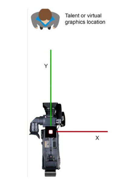
Generally, the StarTracker Y axis will point towards the talent or graphics location, and the X axis points to the right, from the camera operator's perspective.
As shown in this illustration the X axis is perpendicular to Y. Use tape or targets on the floor to set up and measure the O-X distance. The position of the origin can be relocated later.
StarTracker follows the Right-Hand Rule; positive X to the right, positive Y forward and positive Z (H) up.
Some virtual set software define Y as up and Z as forward. In this case swap or reverse axes within your virtual set software, to have them correspond to StarTracker.
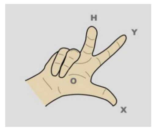
Discuss with the production team where talent or virtual graphics will be and make sure you setup the axes the correct way. In general, the StarTracker Y axis will point towards the talent or graphics location, and the StarTracker X axis will point to the right from the camera operator's perspective. As shown in illustration below, the O-X axis is 90 degrees opposed to O-Y, with X to the right of O-Y. Use masking tape set up and measure the O-X distance (note that the position of 0 is for setup and reference. Its position can be easily relocated later).
0-X is roughly ½ of studio height.
The greater the O-X distance, the greater the accuracy of the StarTracker mapping to the studio. Be as accurate as possible when measuring and marking the O and X positions.
**IMPORTANT: Referencing is required when the sensor unit will not be mounted directly to a camera (e.g. object tracker, mounted to a base of a crane or embedded in robotic head.)
If the sensor is mounted to the camera this section can be skipped and you can go straight to Auto-Aligning (P.28)!
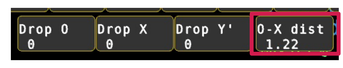
Mark O, X and Y on the studio floor, using tape and a pen for reference points. Be certain to measure accurately and use the same part of the sensor body each time you move. The O-X distance will be used later to scale the map units to real-world units.
When dropping O (origin) and X it is critical to keep the pan value the same, to avoid pivotal offsets affecting measurements. It’s not necessary, when moving the sensor, to move in line between points, or even remain on axis. The system will ignore movements between points and automatically build the Y axis at a 90 deg angle to the O-X line. It is, however, important to maintain the same height and ensure you are placing the sensor unit on the same side of the axes line
Shown below the red and green lines on screen illustrate the direction of the x and y axes on the map. By holding a finger over the ST sensor and aligning it with one of these lines, you will see how the direction of the axes relate to the real world.
![]()
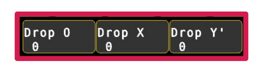
To begin move the ST sensor to the O position. Go to Mapping → Create , click Drop O. It won’t show changes in the map as it is only regarded as a temporary marker. If you are successful a message will flash briefly below saying “Added pose datum”.
The number displayed in the button increments each time you successfully drop the origin, O. The value of that number doesn’t matter, it is simply a success counter, similarly for X and Y.
Seen here as a zero-value having not been dropped yet
Ensure you have OPTICAL GOOD status when dropping O or consider a different location.
Next move the sensor to the X marked position on the floor and click Drop X Finally move to the Y position and click Drop Y Maintain the same physical height on the floor as O & X. The distance of O-Y is not crucial, but should be like O-X. Points O,X & Y do not have to be dropped 90deg relative to each other. Just ensure that the Y point is to the left when looking at X from the O point. The O-X distance should be roughly half of the star height for good results.
Transform the map in Map Transformations: All and type Y to confirm. The map should snap into place and message will report “Successfully transformed map”. Click again if you are unsure – the map will not change again if you successfully transformed the map. Mapping should be off.
To verify the height levels, go to various locations known to be the same height on the real-world studio floor, and compare the height with the StarTracker screen reading.
To verify scaling move the sensor in the real world along X or Y axes and confirm StarTracker reports a similar value.
To set the StarTracker height, place the sensor on the floor and measure from groove with CCD Mark. Go to Mapping -> Create -> Height and enter the height in meters and hit enter.
If you would like to relocate the origin move the StarTracker sensor to the new position, press Drop O and Set O
Alternatively, you can also use Set as map origin function in Offsets → Verify once the sensor is mounted and the system is Auto-Aligned.
You can manually translate (move) the map position in X,Y,Z (Z=Height) and rotate it about its origin.
Note that this is different to moving/rotating the offsets between the sensor unit and studio camera CCD, which are set in the Offsets menu.
You do not need to have tracking to be able to do this; only a loaded map
Go to the Mapping → Transform menu
This part of the menu controls the linear X,Y,Z translation of the map.
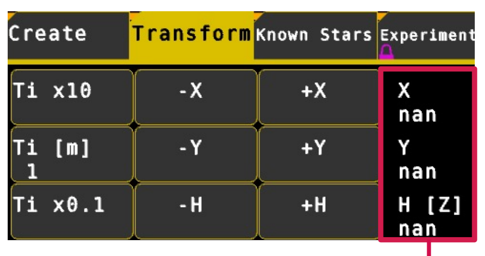
This part of the menu controls the rotation of the map about its origin.
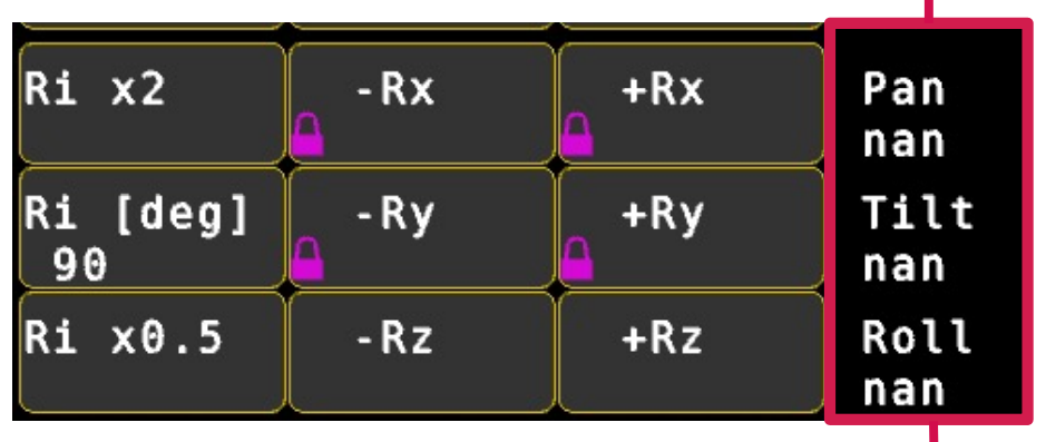
Go to Mapping → Transform This controls linear X,Y & Z translation and rotation. The map is moved by either Ti for linear translation in metres, or Ri for rotation in degrees.
To change manually click on Ti or Ri and enter the increment at the bottom. Values can be changed by a factor of 10 by clicking Ti x10 or Ti x0.1. Rz rotates the map without tilting it, similar to pan. Rx and Ry tilt the map eg: select +Rz to increase rotation, you will notice StarTracker pan increase by 10. You will also likely see the StarTracker X & Y position change. The map rotates about its origin, O not current StarTracker position. Do not use Rx and Ry unless you intend to manually tilt the map – They are locked to prevent accidents.
To save the translated/ rotated map type s. The * will disappear from the map name at the top of the screen. The yellow [MAP MODIFIED] indicator at the top of the screen will disappear. If you make a change to the map that you do not want, simply reload the map, type L, without saving it to remove changes. In this way you are free to experiment with translations/ rotations non-destructively.
If you have more than one StarTracker system, the map can be shared. Copy the map onto a pen drive and then paste it into the map folders of the other systems.
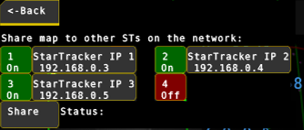
If you have multiple StarTrakers on the same network, the map can also be shared within the software. Go to Mapping -> Manage -> Share Map. Enter the IP addresses of up to 4 StarTracker devices. THen hit share button. The staus will then show "OK" or "Fail" for each of the devices.
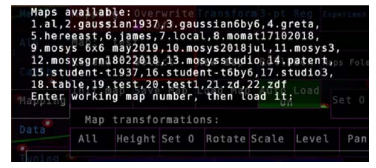
A StarTracker can contain a multitude of maps. To switch between maps, go to Mapping → Select and choose the map, type in the working map number and hit enter. Load the map, press L and Y.
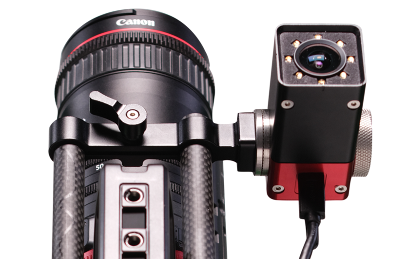
To mount sensor camera bracket to broadcast camera handle use supplied Imperial ¼ x ½ screw. Square it to the broadcast camera and make sure it’s secured with the two supplied studs mounted to the bracket to clamp it to the camera handle. Make sure the bracket is mounted tightly, so it can’t move. It should be square to the camera, pointing straight down the lens line.
StarTracker comes with different brackets. Make sure the StarTracker sensor camera is facing the right way, with the USB-C umbilical cable pointing at the back.
To mount the processor unit, you can use the 15mm rod processor bracket.
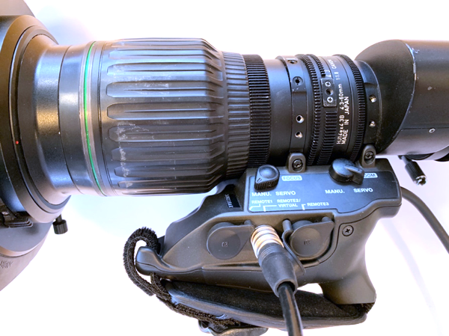
Mo-Sys offers external lens encoders for Fujinon and Canon ENG type lenses and a variety of film lenses. There are three different types of gearwheels provided with these types of encoders. They are interchangeable using a Phillips screwdriver. The coarsest gearwheel fits film lenses. The medium coarse fits the Fujinon ENG type lenses. And the finer gearwheel fits the Canon ENG type lenses.
There are 2 kinds of lens encoders: two-split and three-split gives you in addition to Zoom and Focus, also an Iris Encoder.
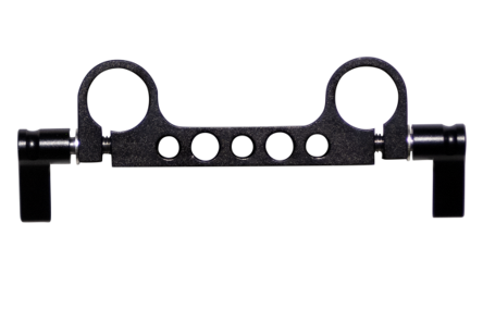
There is a custom bracket for ENG type lenses and brackets for 15 and 19mm rods.
When mounting make sure the encoders are spring loaded. Push the spring whilst tightening grub screw. The gears should be running smooth and there should be no audible clicking when running the lens.
There are 2 ways to calibrate the mechanical lens encoders. Another name for zeroing the encoders is to "do the lens ranges"
Through Software:
In Data -> Lens click Zero Lens. Then move the zoom and focus lens to their physical end-stops a couple of times
Set the encoders you are using to "Activate". Turn off the ones you aren't using.
Through Hardware:
To reset lens ranges, press the Zero lens button on the processor. The button is recessed and you need a thin pin tool to press it (e.g. toothpick, sharp pencil. smallest Allen key from the tool kit.
After this you need to show the lens ranges, moving the zoom and focus lens rings to their physical end-stops a couple of times.
Mo-Sys offers Digi Lens interface for most Fujinon and Canon ENG type lenses. If your lens servo has a port that says "Virtual" it is compatible. But if in doubt please contact us.
Note: When using Digi Lens make sure that the camera and lens is powered on before you power on the StarTracker. If the lens has no power StarTracker software will show an “I/O error”. To fix it, check there is power to the camera and lens and do a complete power reboot of the StarTracker. A restart of the processor using the power button alone will not solve the problem. A complete power cycle (unplug PSU, wait 30 seconds and plug it back in) is required.
Offsets are applied to account for the difference in position between the StarTracker sensor and the CCD plane of the broadcast camera.
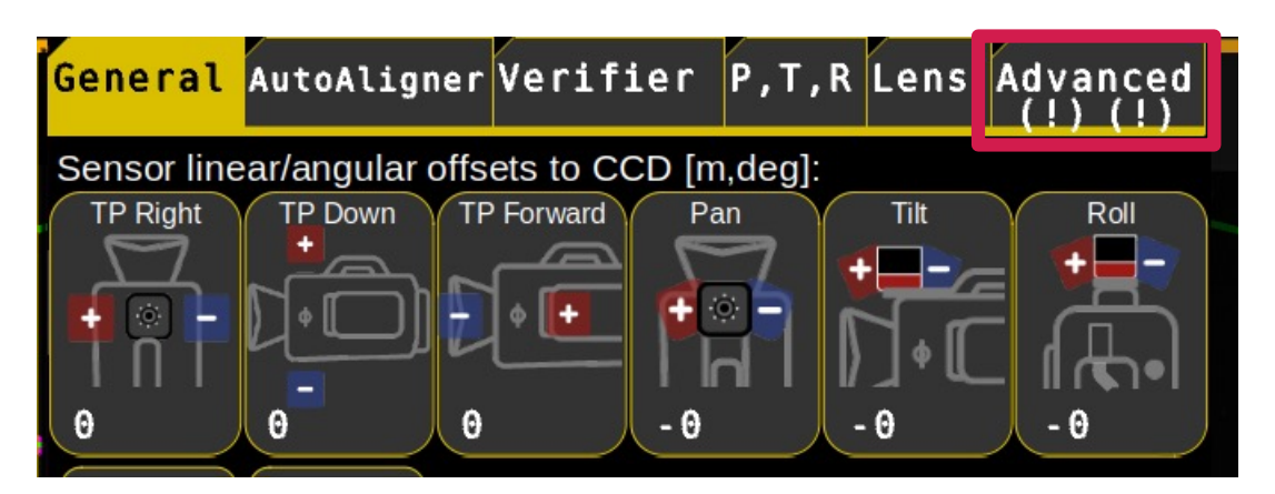
For clarity check Main → Pose Display to confirm, in the data output panel, what is being displayed and check the Offsets menu for existing offsets.
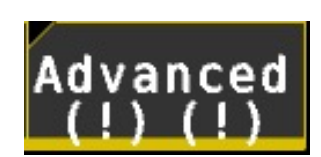
If no offsets are present the Advanced button will be blank. If there are offsets the button will have exclamation marks. The left exclamation mark indicates that there are map offsets, the right exclamation mark indicates that there are Scaling offsets. If that’s the case, click on Advanced and change offsets to 0 and Scale to 1.
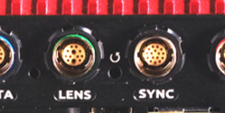
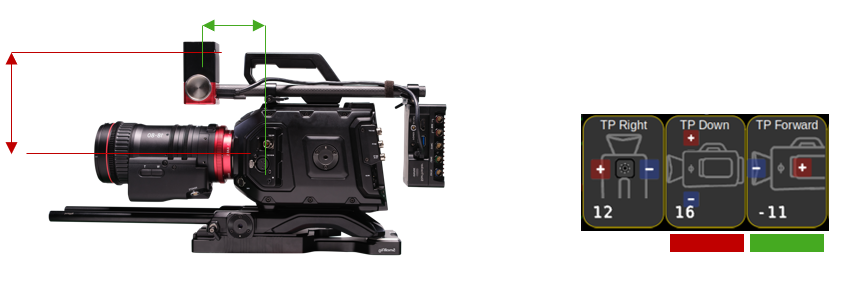
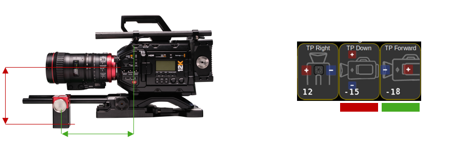
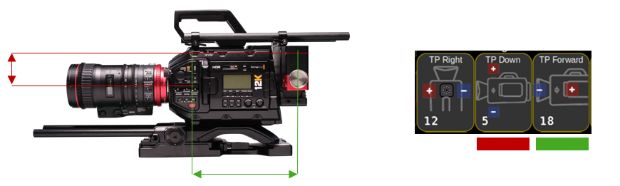
Broadcast cameras usually have an indicator for CCD location along the camera body. Vertically it’s in the centre of the lens but where no symbol is displayed check with the camera manual and use a tape measure.
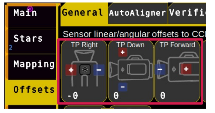
TP Right is positive as we move it to the right.
TP Forward is negative as we move the tracking point backwards.
TP Down is positive when we are moving the tracking point down.
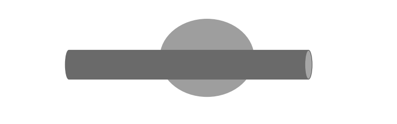
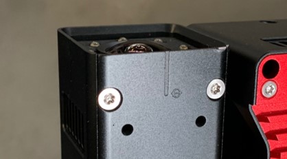
This is the position of the StarTracker sensor CCD. It is vertically located at the groove and CCD Mark.
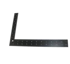
For measuring accuracy, use the square ruler, if provided with the StarTracker kit.
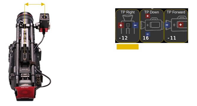
Note: The sensor cable should ideally point towards back of the camera if possible. But don’t worry if it isn’t, as Auto Aligner will calculate the exact offset
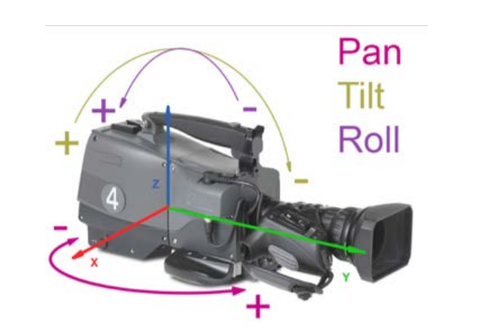
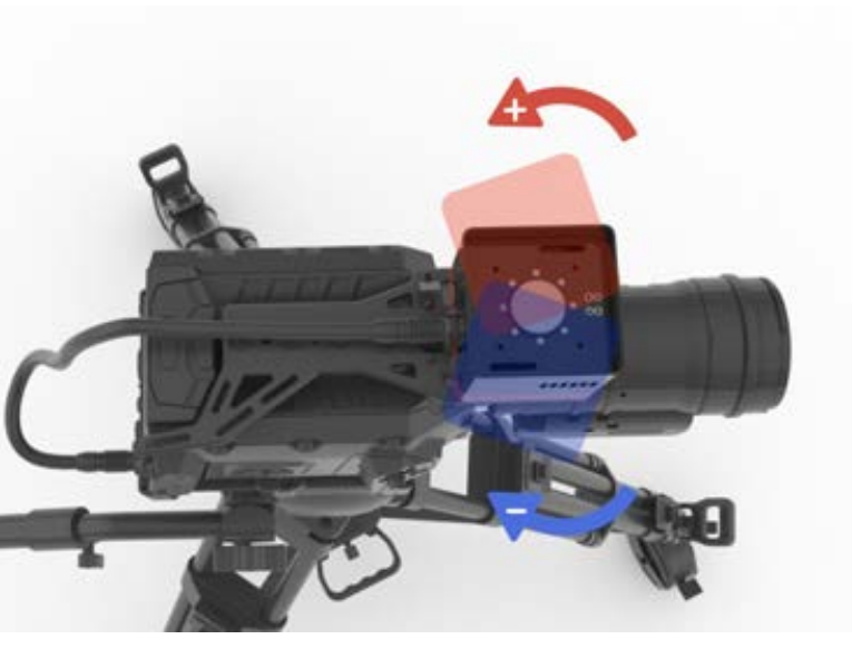
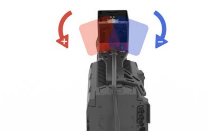
Pan is positive when camera is panning to the left.
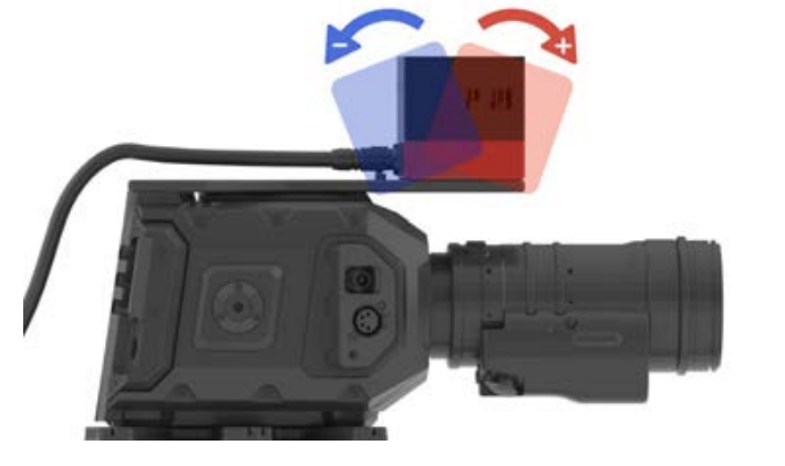
Tilt is positive when camera tilts up.
Roll is positive when camera rolls clockwise.
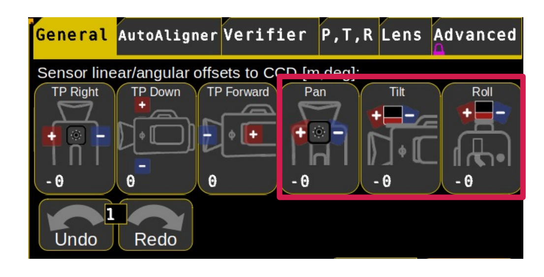
Angular CCD offsets can be set in Offsets → General
Pan Offset
Tilt Offsets
Roll Offsets
Pan and tilt offsets will be calculated by the Auto-Aligner! Roll offset needs to be set checking against graphics.
The Roll offset needs to be set prior to Auto Aligner if there is an obvious roll offset (>2 deg). If you use our standard broadcast bracket the roll offset can be left at 0.
You can use an electronic angle measurer (also phone app) to get the correct roll value. Make sure the broadcast camera is fully levelled in roll when measuring the sensor unit roll offset.
For the closest match of virtual graphics to real world camera the StarTracker offers through-lens calibration to tweak offsets that were set during the mapping and calibration processes. You will need to have the ST sensor unit rigidly mounted on the studio camera, have performed the mapping and O,X,Y map alignment and ST sensor calibration steps.
Before commencing with the Auto-Aligner makes sure you have measured and entered your TP Right, TP Down and TP Forward accurately (see camera offsets).
The Auto-Alignment process will involve marking 3 known reference points in the studio and gathering several observations of them by looking at them through the centre of the studio camera lens. From this the system will automatically tweak the map and camera offsets to try to give tracking data that best matches these viewpoints.
Note: This calibration process cannot tweak the “TP Forward” or “Roll Offset” values, as set in the Offsets menu.
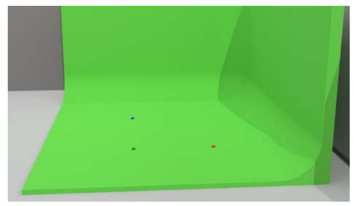
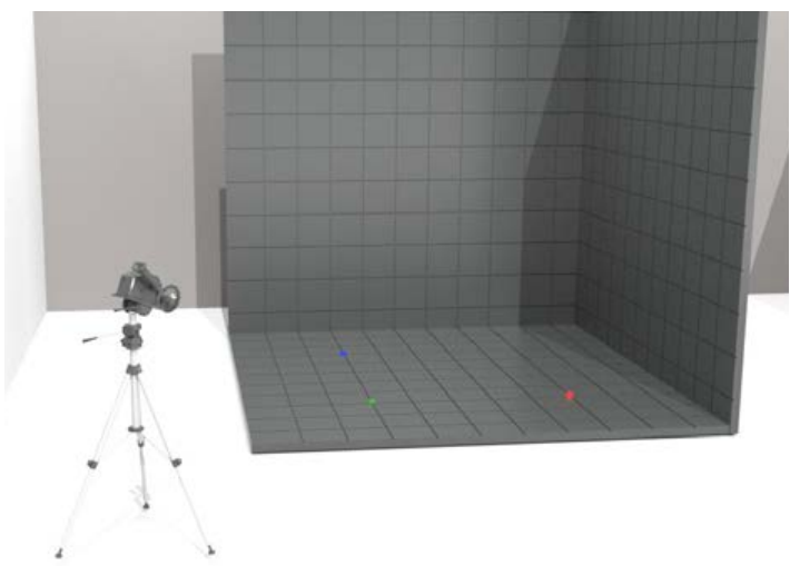
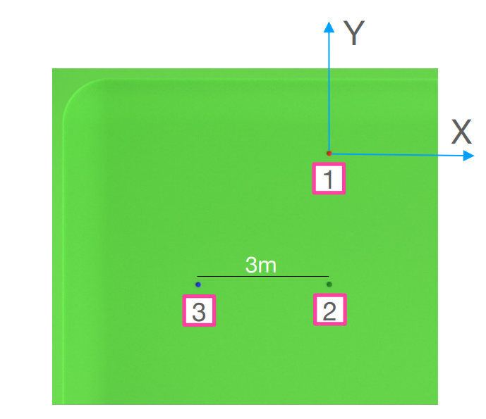
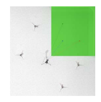
To start, measure and mark 3 points on the studio floor whose 3D positions relative to the map origin (0 position) you can measure accurately in X, Y and H (height). In the below image the red marker is our zero point. Ideally the marked points should be in an area of the studio where the talent will be later and where the cameras are mostly looking at.
If you have an Auto-Align kit, assemble it accordingly.
If you have an LED volume with floor tiles you can use the tiles as reference. See image below:
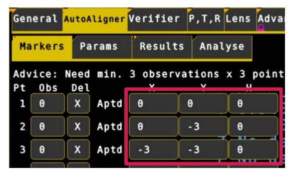
Then go to the Offsets → AutoAligner menu and select the Markers menu at the top. In the blue boxes, enter the 3D positions of the reference points you measured. For instance, you would enter the known X,Y,H coordinates of point 1 in the boxes marked X, Y, H. The units are in meters.
If you have measured fewer than 6 points, ignore the rest. You should measure at least 3 points, or the system will not calibrate. In the screenshot below, three reference points have been entered so far, point 1 being the zero point shows the coordinates 0, 0, 0.
These points are automatically saved to prevent you having to re-enter them if you restart the software.
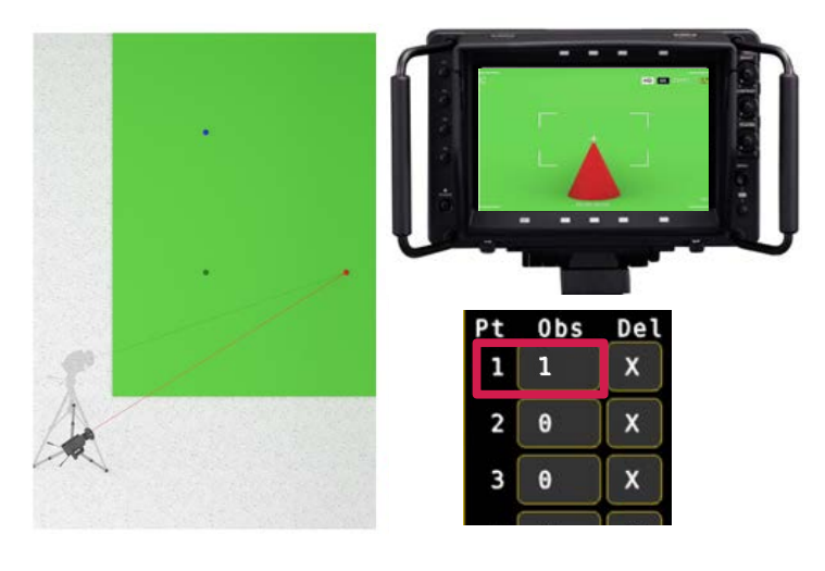
Create a crosshair in the centre of your studio camera image to help you with the observation phase. Most cameras or virtual set software allow you to create a crosshair in the centre of the image.
Start by looking at point 1 through the studio camera, aligning it in the centre of image. If you are using the Auto-Align kit center the tip of the cone. The closer to the centre of the image you are when you add the observation the better the calibration will be. You do not need to observe the points in any order, provided you add the observation when you are pointing at the corresponding point X.
Then click into the Obs field next to Pt 1 to add that observation of point 1 to the system. The number should increment if successful.
Note: If there is a problem, for instance you pressed the wrong point or the point was not in the centre of the image, press the X icon button to the left of it to delete the last point observation. The number should decrement.
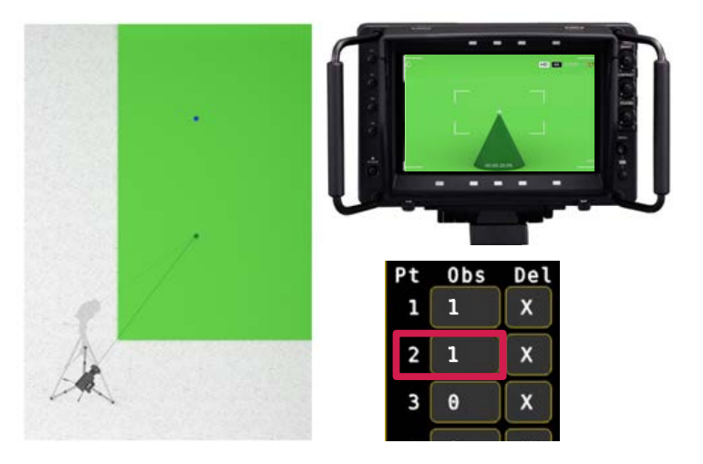
From same camera position now look at point 2, center it and click into the Obs field next to Pt 2
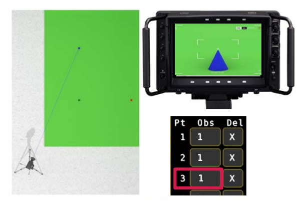
From same camera position now look at point 3, center it and click into the Obs field next to Pt 3
Make sure the tracking status shows “Optical Good” at all time when taking the observations. If you are too close to a wall and you tilt down it is possible to lose the tracking and the Auto-Align will not allow you to add an observation or give a bad result.
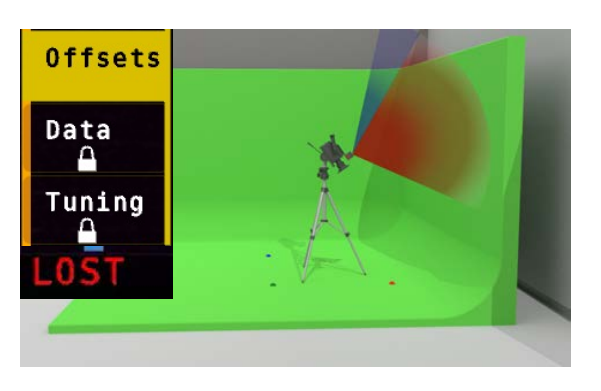
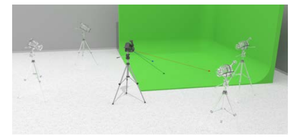
Take the 3 observations of the points carefully from at least 3 camera positions. Best practice are 4 to 6 (image above shows 5 camera positions with a variation of camera angles and distances to the points) .
For the best calibration, each point should be seen from a variety of angles and distances. If you know where the studio cameras will operate and where the set is, you can focus your observations from these positions.
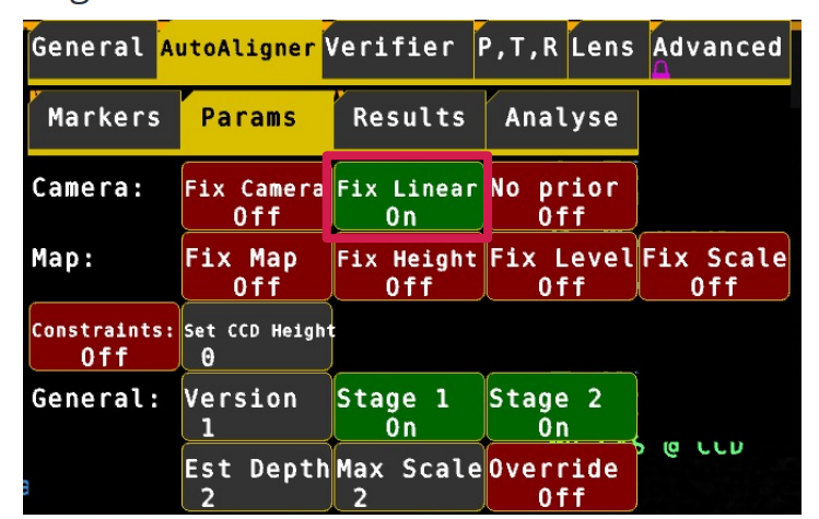
Once you are happy with the observations made, click on Offsets → AutoAligner → Params All buttons should be off, except Stage 1, Stage 2 and Fix Linear should be on. Fix Linear locks CCD offsets. Make sure you measured them accurately and entered them accurately into the TP offset fields in Offsets menu before performing an AutoAlign.
Note: The calibration process cannot tweak the “TP Forward” or “Roll Offset” values – these should have been set using the steps before and are not modified by this calibration.
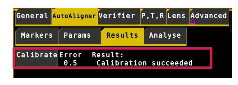
Click on the Results menu at the top, then click on Calibrate. The optimisation error and result will be shown to the right of the Calibrate button. In general, you are aiming for a low error, ideally less than 1.
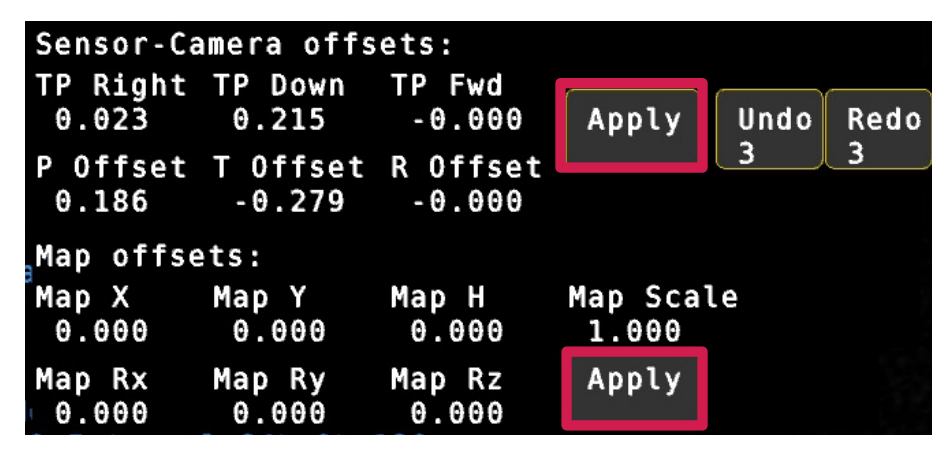
If the result says, “Calibration succeeded”, the calibration worked, and you will see the calculated offsets. Check they look sensible. For the Sensor-camera offsets, check the linear and angular offsets look about right.
You can apply the calculated offsets to the camera and map, by pressing the Apply button next to the Sensor-Camera offsets.
Look at the “Results” status to see if there was a problem applying the offsets
The TP offsets applied are saved automatically and will show up once you go back to the Offsets menu.
If your Verify values (see next section) are off do a second calibration round. Go back to Auto-Aligner -> Results and hit Calibrate again. Then hit all three APPLY buttons. Now verify again
If you are happy with the results in the Verifier, save and load the map.
Unlike the camera offsets, the map needs to be manually saved when the offsets have been applied. You will see the usual “Map Modified” and * indicator show up in the GUI if the map has unsaved changes.
After having calibrated and applied the CCD and map offsets you can verify the points and the accuracy of the result with the Verifier tool.
Make sure you don’t have any offsets in Offsets → Advanced in Set X, Y, H, Rz, Rx, Ry. Indicated by exclamation marks.
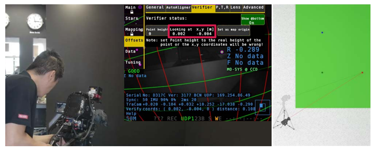
Go to Offsets → Verifier.
Look at any of your reference points. Fully zoomed in and using cross hair.
In the Verifier status, you can see “Looking at x,y (m)” values displayed. These are the calculated positions in meters for the point you are looking at
The error is proportionate and can vary depending on studio size but should not be higher than 2cm (in the example below the 0 point on the floor is out by 2mm in X and 4mm in Y).
f your reference point is not on the floor put the height value in meters into Point Height. In our studio example the Point Height is 0.
If your reference point is in 10cm height put Point Height to 0.1.
You can also use the Verifier to shift your map origin.
Look at your new zero point and click Set as map origin. Then save the map.
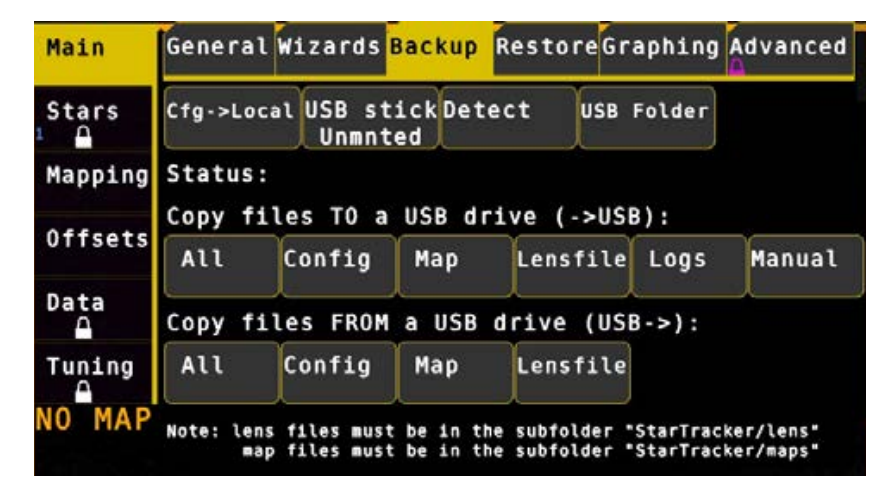
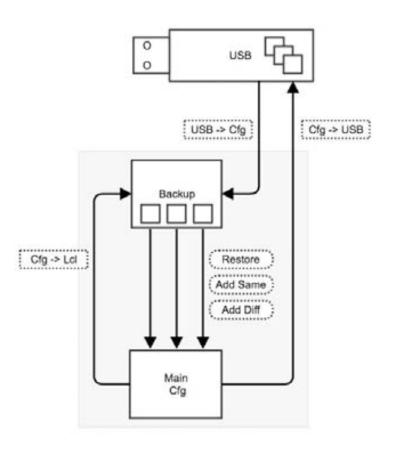
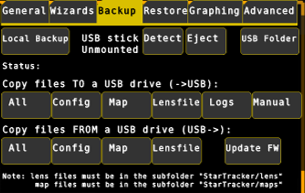
Backup maps, config files, logs and user manual to/ from USB stick. Insert a USB memory stick into the StarTracker and a directory window will open. Close it. Click Main → Backup → Detect until it displays “USB Stick Mounted”
Under “Copy files TO a USB drive” click Maps to copy maps to the USB stick. Repeat for Config, Lensfile, Logs or if you want to backup everything All.
Click Main → Backup → USB stick until it displays Unmnted as unmounting will ensure the files are copied correctly to the USB stick. Only then can the USB stick be removed from the StarTracker
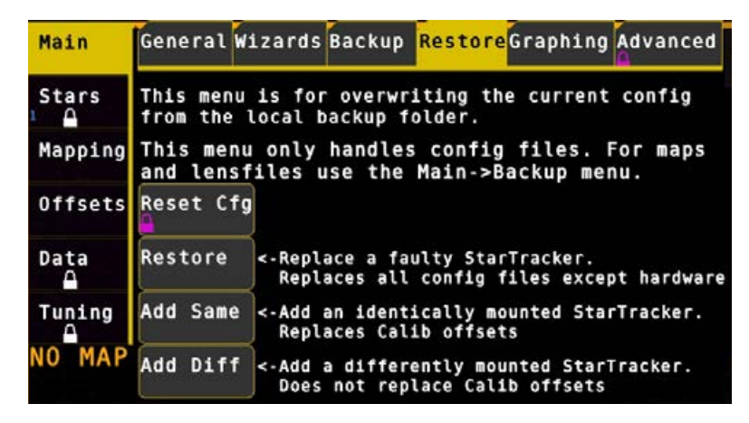
Maps may be shared between devices. Copy the map onto a USB stick and paste it into the map folders of the other systems. Go to Mapping → Select Map choose the new map, load the map, press L and Y. You can choose how your back-up Cfg file is applied.
Main → Restore restores all the settings, including CCD offsets and network settings.
When you click on the Restore button it shows a list of configuration files with a time stamp. One of these is marked as Factory cfg settings. Use it to restore StarTracker to factory settings. Be aware that this clears all settings that have been modified during installation.
Add Same (same sensor offsets) copies all settings, excluding network settings, Use this when setting up an identical StarTracker with the same CCD offsets.
Add Diff (different sensor offsets) copies all settings, excluding CCD offsets and network. Use if the second StarTracker has different CCD offsets.
Before configuring StarTracker to stream data to the virtual set PC you will require the IP address of that Virtual Set PC.
Once you know this IP head to Data → My IP in the StarTracker and select Eth1.
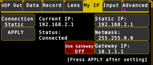
Choose your connection method.
DHCP - if the IP address and netmask of the StarTracker should be assigned by a DHCP server on your network. Please note the rendering engine should also be on this network!
Local - if the StarTracker is directly connected to a Windows PC via an ethernet cable (i.e., no network), Windows will negotiate a point-to-point IP address for itself and the StarTracker. This will usually be an IP of the form 169.254.x.y.
Static (recommended) - use the IP and Netmask settings in this menu to give the StarTracker a static IP with corresponding netmask. The IP and netmask must be appropriate for your network and network settings of your rendering engine!
If your StarTracker has an Auto Connect button, turn this on to re-apply the network settings automatically if the ethernet cable is reconnected (recommended)
If your StarTracker has a set on boot button, turn this on to apply the network settings on system bootup (recommended)
It could take up to 5 seconds for the StarTracker to recognise the connection change and re-apply the network settings. If your StarTracker displays the Current IP: in the network menu, the IP will change to reflect your current IP, or show 0.0.0.0 if not connected.
The StarTracker may pause for ~10 s after setting the DHCP or Local method - this is normal. The Static method usually applies instantly
Press APPLY after changing the method and/or IP settings you require, or the new network settings will not take effect!
Go back by clicking Output.
Put the IP of your virtual set engine into Destination IP 1 field.
The Protocol button next to Send UDP allows you to select the protocol to either (Mo-Sys) F4, D1 (freed) or PSN (Posi Stage Net).
Use the second and third “Destination IP” row if you need to send the tracking data to two different engines. You can send to a different IP and port and also send the data in a different format (e.g., F4 and D1).
Put the IP of your virtual set engine into Destination IP 1 field.
The Protocol button next to Send UDP allows you to select the protocol to either (Mo-Sys) F4 or D1 (freed).
When you enable LED mode, the data will be sent with lower latency and other settings are applied to optimise use within LED volumes.
Use the second and third “Destination IP” row if you need to send the tracking data to two different engines. You can send to a different IP and port and send the data in a different format (e.g., F4 and D1).
StarTracker versions later than 1310M have a Ping Test option in the Network menu. Pressing this button will automatically ping the target IP set in the Data → UDP Out menu and return either OK or FAIL. Wait up to 10 seconds for the test to complete.
Failure indicates an inability to ping the target machine (no route or response), indicating the tracking UDP packets are unlikely to reach the target machine. In this case, check:
Is Windows firewall enabled on the target machine? This can block UDP packets from the StarTracker
Have you set the IP settings of the target computer correctly?
Are the IP/netmask settings for the StarTracker and UDP target compatible?
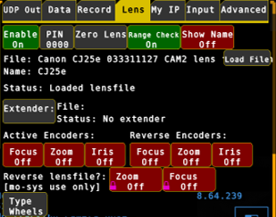
If you are using a Mo-Sys Lens File, make sure you enable it either in Data → F4 Lens or in Data → Lens Data → Enable (same button)
To load a lens file, go to Data → Lens Data → Load File.
Select the lens file from a list, type the number and hit enter.
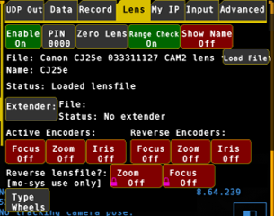
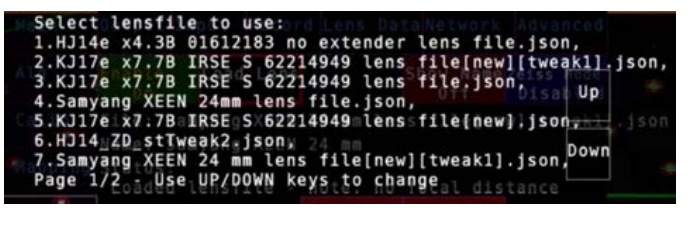
The lens files are stored in runtime/lens as .json files or .dat files, if tweaked in UE5.
Show Name shows the name of the lens at screen bottom.
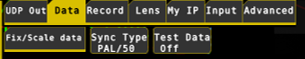
Enter your intended Genlock in Data > Sync Type. Click repeatedly until your desired sync value is displayed; 24p, 25p, 30p, PAL, NTSC, Unknown.
Any analogue sync signal will be accepted (Blackburst, TriLevel).
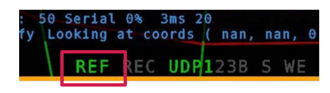
If the REF symbol at bottom of screen is green you know the unit receives a good sync signal, also the number on bottom left should be green.
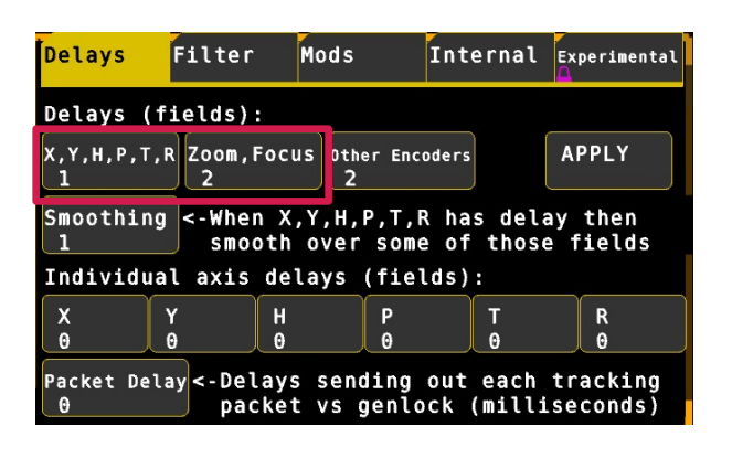
Pan camera from side to side in short sharp steps to observe any delay between the virtual graphics and live image output. Repeat for tilt. If the pan/tilt graphics are too fast increase Tuning → Delays → X,Y,H,P,T,R to match graphics with the live image output. The delay can be set in increments of 0.5 fields/frames (2 fields = 1 frame).
Sometimes pan and tilt delays do not match. In this case you can add delay to individual axes.
Having set the delay for all axes you will then need to set the lens delay choosing Tuning → Delays → Zoom, Focus.
Individual axis delay in Advanced Mode: in addition to X,Y,H,P,T,R by setting Tuning # Delay where # is the axis to delay e.g., Y Delay - Any increment value is supported here.
After changing delays hit APPLY button
The StarTracker can also be used facing down. The sensor camera is inverted and looks at small retroreflective stickers on carpet/fake lawn/lino/studio floor.
Apply stars to the floor. The distance between stars should be a tenth of height from floor to sensor.
Make sure the floor is flat and avoid any bumps.
The floor should not be too soft as the stickers might sink in when camera operator steps on floor.
Mount the sensor unit facing down. Get into touch with us if you need bracket solutions
In StarTracker go to Stars → Type and click Unload (If you have map loaded).
Then change to Floor-Facing. After a few seconds Current should change to Floor-facing. If it doesn't happen, you need to do a Main -> Restart.
Mapping and Referencing process (AutoAligner) are the same as with ceiling facing sensor.
It's the same process for Horizontal tracking (e.g., forward facing, side-facing, backward-facing)
![]()
Firmware file sent via Wetransfer, email or download link.
Plug USB Stick into StarTracker. Close the file manager window that pops up.
Go to Main -> Backup and click on Detect. Make sure the status shows "Mounted"
Then click Update FW. It will give you a list of the zip rules it found on the USB drive. Select the one you want to update and hit Enter.
Then make sure the status says "Updated firmware. Restart to use new software. IF it shows some error, contact support@mo-sys.com
Click on Eject to remove USB stick and go to Main and hit Restart.
To upgrade boot StarTracker into Engineering Mode:
Shutdown StarTracker if currently on (use power button top left)
Power on StarTracker (use power button top left)
Keep tapping down arrow key
Sub menu will be displayed
Select Engineering Mode (usually second in the list.
When system is loaded insert USB drive
Right-click firmware folder (e.g., r3170 BCN)
Select Open Terminal Here
In Terminal type: bash ./install./install.sh
Message at the bottom should say "Successful"
If you update to a version higher than 3105 you need to type: sudo ldconfig
Close Terminal
Back in StarTracker software Main -> Restart
Check and verify firmware has updated (located bottom of ST screen "ver: xxxx")
The tracking test signals replace the real tracking data coming out of the StarTracker with fake data created completely independently of the optical / gyro sensors and filtering (for instance a constant pan with other axes fixed). Thus, moving the camera during a test signal will have no effect on the graphics.
This allows you to determine whether tracking data problems are due to communication (e.g., genlock, network or RS422 issues), virtual set issues (e.g., scene too heavy) or the quality of the tracking (e.g., optical noise, gyro noise), as it is rarely obvious which is to blame for jitters, stuttering and other effects.
The test signals will often save you time digging around and playing with StarTracker Tuning & Data settings by ruling out optical & gyro noise if the issue is not due to the tracking quality.
Press Data → Test Data to cycle through the available test signals. The last setting will be “Off”, which provides normal tracking. The most useful test signal types are:
Inc pan: This fixes X,Y,H,T,R at constant values and pans the virtual camera at a constant speed. Zoom and Focus are unaffected and function normally. If the virtual camera does not pan smoothly in this mode, then the problem is not tracking quality but either a communication/genlock or virtual set problem.
PT Jump2: This jumps between two sets of X,Y,H,P,T,R values alternating every field: X,Y,H,P,T,R→X,Y,H,P+5,T+5,R→X,Y,H,P,T,R→X ,Y,H,P+5,T+5,R→X,Y,H,P,T,R→…. Zoom and Focus are unaffected and function normally. You should see two virtual objects overlaid on each other, one panned and tilted by +5 deg relative to the other. If there is a genlock or other sync problem that means only odd or even fields are rendered, or fields are dropped, or the tracking is not synced properly to the virtual set, you may see: - only one graphic image rather than two overlapping graphics
one graphic image become “solid” for a moment
graphics “swap places” or move around
unstable flickering or brief jumps in the graphics
This shows there is a problem in the genlock or synchronisation rather than a tracking quality problem.
General Causes:
Incorrect or unwanted offsets in the StarTracker or virtual set software.:
Lens:
Direction of encoders (can be reversed in StarTracker (Data –> Lens Data)
If you zoom in and your graphics get smaller Zoom direction needs to be reversed
Focus is harder to identify. Because of lens breathing (changing of FoV when focusing) you can use the same method as with Zoom, watching the graphics get smaller or bigger in correspondents to the background video when changing the focus. If it doesn’t match, Focus direction needs to be reversed.
Lens limits (ranges) not set or incorrect
Non-offset tracking issues - Local map position or height error (i.e., only in certain places) Scaling of map not quite correct - Real-world mismatches Curved studio floor assumed to be flat, especially where O,X,Y was dropped Loose screws or sensor mounting bracket unmounted and remounted
Generic through-camera tool 1. Choose a reference point you know the coordinates of to look at, e.g., the origin: - In Offsets→ Verify click on “Ref pt” so it says “Centre”, then enter the height of the reference point you are looking at in “Ref H [m]”, in metres. E.g., if the reference point is on the floor enter 0. - Place a crosshair in the real image, e.g., through the camera viewfinder, zoom fully in and pan/tilt the camera to align the reference point in the centre of the cross hairs, as you would have done in the auto aligner. - The X,Y coordinates of the point, in metres, that the StarTracker thinks the camera is looking at will be shown in “Ref x [m]” and “Ref y [m]”. - If this is close to the correct coordinates of the reference point, but the virtual object is further out, then there is some sort of offset or lens issue in the virtual set software.
Offsets Checklist
Check there are no unexpected offsets in the StarTracker in Offsets → Advanced and that the scaling values are all 1 (or -1) as relevant.
Check that there are no unexpected offsets in the tracking, map or reference object in the virtual set software.
Check that you have set the lens limits (zoomed fully in and out, focused fully narrow and wide), and that the lens encoders firmly engage the lens without play.
Check that the coordinates of the points you aligned to in Offsets → AutoAlign → Markers match the coordinates of the objects you are using to verify alignment.
Check that the Output (studio cam) values in StarTracker match the tracking values in the virtual set
Follow the through-camera, position sanity and lens checks above to diagnose where the problem lies.
Real-World Issues
The StarTracker is an optical system so will be subject to local errors and error build-up as you move away from the origin. These cannot be removed by any offsets as they are “non-linear”. However, if the errors are large that is usually a sign of something wrong
If the virtual set design assumes that the floor is flat, but it actually curves or dips in certain places, even with perfect tracking the graphics may not exactly match the real in all places as the position of the real floor will be off relative to the virtual floor.
If the StarTracker sensor mount or lens is moved/changed without the knowledge of the virtual operators (e.g., by maintenance technicians) this can result in offsets changing for seemingly unknown reasons. Care needs to be taken when maintaining cameras used for VR/AR as modifying lenses or moving the sensor bracket has repercussions for the lens calibration and sensor offsets, resulting in graphics not matching the real world.
Usually changing the lens results in the “lens centre shift” changing, as this is affected by tiny variations in how the lens is mounted on the camera. See the lens sanity check above for how to diagnose this.
Remounting the sensor bracket usually results in the Offsets P/T/R Offsets (i.e., angular offsets) slightly changing.
General Causes:
Hardware: - Ethernet cables not connected - Faulty ethernet cables - Misconfigured or firewalled switches/routers - Faulty hardware in StarTracker, virtual set machine or switches/routers
Software: - Windows Defender firewall turned on in the virtual set software - Incorrect network IP/netmask settings in the virtual set software or StarTracker - UDP data sending turned off in StarTracker - Incorrect interface or network method specified in StarTracker
Checklist
Verify that the ethernet cable is connected on the StarTracker and virtual set machine sides, and that the orange/green lights on the RJ45 socket are blinking.
Verify the IP address of the correct network adapter in the virtual set machine following the networking steps in the StarTracker manual. The virtual set machine may have multiple network adapters, in which case ensure you are looking at the correct one!
Verify the connection method in the Data → Network menu of the StarTracker is appropriate to the physical network type between the StarTacker and virtual set machine, and that the IP address and netmask of the StarTracker is correct and compatible with the virtual set machine. See the networking steps in the StarTracker manual for guidance
Verify that the IP address shown in the status display in the Data → Network menu is sensible and says connected (static method) or Unknown [DHCP/link local]
Verify the IP address and port in the Data menu corresponds to the IP and port of the virtual set machine, protocol is correct (e.g., Mo-Sys F4) and that Send UDP is turned on
Verify that Windows Defender firewall is turned off on the virtual set machine as this often blocks UDP packets from the StarTracker. Note: it sometimes turns itself on even if it was turned off before!
Click Data → UDP Out → Ping 1,2,3 to ping the IP of the virtual set machine. Wait 5s for the test to finish (“…” will show) – It will either show “Ok” or “Fail”. If it shows “OK” then the StarTracker can “see” the virtual set machine and something else other than networking may be wrong, such as protocol, port or configuration settings in the virtual set software
Try to ping the StarTracker IP from the virtual set machine. If this succeeds the virtual set machine can see the StarTracker so there is a network connection between them